Leave Your Message
*Name Cannot be empty!
* Enter product details such as size, color,materials etc. and other specific requirements to receive an accurate quote. Cannot be empty

Why Choose a Cyclone Cluster for Dust Collection?

A well-designed dust collection system does more than pull visible dust from the air. It must handle changing production rates, protect downstream filters, and keep material moving reliably. A Cyclone Cluster can help meet those demands by placing multiple cyclones in parallel. This arrangement can accommodate larger airflow while separating heavier particles before they reach final filtration. Less dust reaches the filters.

The U.S. Environmental Protection Agency’s Air Pollution Control Technology Fact Sheet, “Cyclones,” reports typical collection efficiencies of 70–90% for conventional units and 80–99% for high-efficiency designs. These figures are not guarantees: particle size, dust properties, airflow, and equipment design all affect performance. A cluster’s results depend on proper sizing and balanced flow across each cyclone. That detail matters.

In practical terms, imagine several branches sharing a common duct. If one branch receives too much airflow, separation may suffer across the system. Operators should therefore consider pressure drop, maintenance access, wear, and the performance of downstream filters—not just the number of cyclones. A cluster may offer flexibility, but it is not automatically the best choice for every process. The EPA fact sheet offers useful baseline context; site-specific testing and qualified engineering review are still important when selecting equipment. Dust is not uniform. The right design starts with measured operating conditions, not a brochure promise.
Why Choose a Cyclone Cluster for Dust Collection?

What Defines a Cyclone Cluster in Industrial Dust Collection?

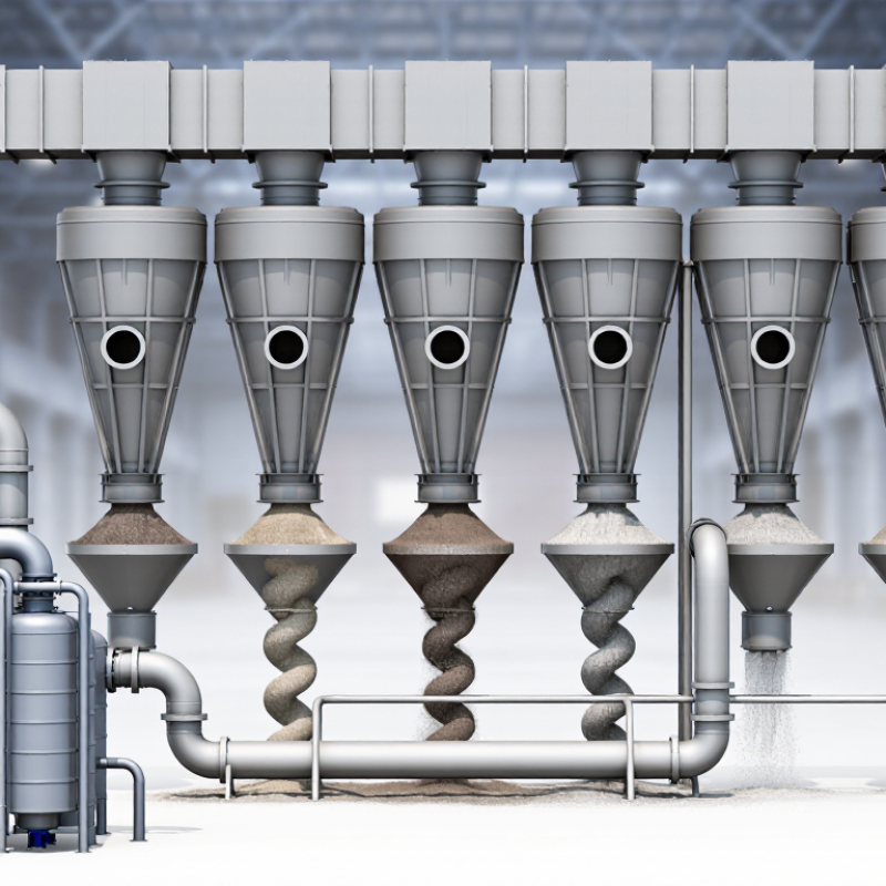
A cyclone cluster is a group of cyclone separators connected to shared inlet and outlet manifolds. Instead of sending all dusty air through one large body, the system divides the airflow among several smaller units. Inside each cyclone, spinning air pushes heavier particles toward the wall, where they fall into collection hoppers. Cleaner air exits through the central outlet. That is the basic idea.

The cluster’s performance depends on more than the number of cyclones. Airflow must be distributed evenly, or some units may carry too much dust while others do little work. Duct layout, particle size, dust loading, and pressure drop all matter. A cluster can offer a compact footprint and flexible capacity, but it is not automatically the best fit. The term itself can be confusing; designs differ in manifold arrangement and maintenance access. Check whether hoppers can be emptied safely and whether each cyclone can be inspected without disrupting the whole line.

Tips: Ask for airflow data at both normal and peak production. Look for access doors, balanced branch ducts, and clear hopper-level checks. Small details matter. A poorly balanced cluster may look tidy on a drawing but collect dust unevenly in practice.

How Parallel Cyclones Separate Particles by Centrifugal Force

A cyclone cluster uses several cyclones side by side to process a larger air stream. Each chamber guides dusty air into a fast, circular path. The motion creates centrifugal force. Heavier particles move outward, strike the wall, and lose speed. Gravity carries them into a collection hopper, while cleaner air rises through the central outlet. That is the basic separation.

Parallel operation divides airflow among units instead of forcing one large chamber to handle everything. When flow is balanced, each cyclone can maintain a stable swirl and separate particles within its design range. This matters in workshops where dust loads change as machines start and stop. A technician can inspect individual inlets, seals, and hoppers for buildup or leakage. Small details count.

Performance still depends on particle size, density, inlet velocity, and the condition of the collected material. Very fine dust may follow the exiting air, so a downstream filter is often needed. It is tempting to assume that adding cyclones always improves capture, but uneven flow can leave some chambers underused and others overloaded. The right sizing is not always obvious. Check airflow and pressure drop under real operating conditions before deciding whether the cluster is working as intended.

EPA Data: Cyclone Efficiency Reaches 70–90% for Total Particulate Matter

A cyclone cluster uses several separators to remove dust from an air stream before it reaches finer filtration equipment. EPA data commonly reports cyclone collection efficiency around 70–90% for total particulate matter. This range is useful, but it is not a guarantee for every installation. Particle size, airflow, dust characteristics, and equipment condition all affect results. Fine particles can be harder to capture. Real results vary.

For a plant handling steady, dusty airflow, multiple cyclones can distribute the load across parallel units. Picture a workshop where a visible stream of sawdust enters the collector: larger particles may drop into the hopper, reducing the burden on downstream filters. However, a cluster adds ductwork and inspection points. Poorly balanced airflow can reduce performance, and a percentage alone cannot show how much dust escapes at a particular particle size. I would not treat the 70–90% figure as a substitute for site testing.

Tips: Check airflow balance and inspect hoppers for buildup. Record pressure readings and dust levels over time. If emissions matter, ask for measurements under your actual operating conditions. Small leaks can undermine an otherwise sensible setup. A detail easy to miss.

How Cluster Design Balances Airflow Capacity and Pressure Drop

A cyclone cluster uses several smaller cyclones in parallel instead of one large unit. This arrangement can handle substantial airflow while keeping each cyclone within a practical operating range. The benefit depends on how evenly air reaches each inlet. A poorly balanced manifold may send more air through nearby units and leave distant ones underused. The cluster can look well sized on paper, yet perform unevenly in the ductwork.

Pressure drop is part of that balance. Each cyclone needs enough air velocity to separate particles, but pushing too much air through a small unit can increase resistance and energy demand. Designers compare the required total airflow with the capacity of each cyclone, then check inlet geometry, duct losses, and the pressure available from the fan. Small details matter. A sharp turn before the manifold, for example, can disturb flow distribution. Access for cleaning and inspection matters too, because accumulated dust may change operating conditions over time. No layout is perfect. Field readings sometimes show differences that calculations missed, so airflow and pressure should be checked after installation, not just assumed from the design.

Where Cyclone Clusters Fit in Multistage Dust-Control Systems

Where Cyclone Clusters Fit in Multistage Dust-Control Systems

In a multistage dust-control system, a cyclone cluster usually acts as the rugged first separator, not the final polishing stage. Parallel cyclones can handle larger gas flows while keeping each unit within its design range. They remove coarse, abrasive particles before air reaches a baghouse or cartridge collector. That matters. Lower dust loading may reduce filter blinding and cleaning demand, though results depend on particle size, moisture, and operating conditions.

The U.S. EPA’s Cyclones fact sheet (EPA-452/F-03-005, 2003) reports conventional cyclone collection ranges of 70–90% for total particulate matter, 30–90% for PM10, and 0–40% for PM2.5. These broad ranges are a warning, not a guarantee. Fine dust can pass through, so downstream filtration may be needed for finer capture. Cluster design also requires balanced inlet flow, sealed hoppers, and checks for wear near inlets and outlets. A poorly balanced branch can overload one cyclone while others do too little.

Tips: Match the cluster to measured airflow and dust characteristics. Check pressure drop and hopper discharge during operation, not just at commissioning.

Why Choose a Cyclone Cluster for Dust Collection? — Where Cyclone Clusters Fit in Multistage Dust-Control Systems
System dimension Cyclone cluster contribution Typical fit or operating consideration
Position in a multistage system Acts as a mechanical pre-separator before finer filtration. Common arrangement: process pickup → cyclone cluster → baghouse or cartridge collector → fan and discharge.
Dust particle range Separates heavier particles through centrifugal action; performance generally improves as particle size and density increase. Often useful for coarse dust, commonly particles above roughly 10 µm. Fine particles, especially below a few micrometres, are harder to capture and usually require downstream filtration.
Parallel airflow handling Multiple cyclones operate in parallel to share the process airflow. Useful when one cyclone would be impractically large or when a modular arrangement is preferred. Even flow distribution across units is important.
Downstream filter protection Can reduce the coarse-dust loading reaching fabric or cartridge filters. May help reduce filter cleaning demand and abrasive wear when the incoming dust contains a substantial coarse fraction. Benefits depend on dust properties and system design.
Pressure drop Adds resistance to the duct system as air passes through the cyclone inlets and bodies. Cyclone pressure drop is design- and flow-dependent; an indicative range for many industrial designs is about 0.5–2.5 kPa. Confirm the actual value with the equipment design and fan calculation.
Dust discharge Collects separated material in hoppers for continuous or intermittent removal. Hoppers and discharge devices should prevent bridging and air leakage; rotary valves or sealed conveyors may be used where the process requires them.
Suitable dust characteristics Works without filter media and has no moving parts within the cyclone body. Often considered for dry, free-flowing, relatively coarse dust. Sticky, fibrous, highly cohesive, or moisture-sensitive dust may require special evaluation.
When a cyclone cluster is not enough It is not usually a stand-alone solution when stringent fine-particle emissions control is required. Pair it with a properly selected secondary collector when fine particulate capture is needed, and verify the complete system against applicable emission limits.
Key selection checks Matches the cluster layout and cyclone geometry to the process airflow and dust load. Assess airflow, particle-size distribution, dust density and abrasiveness, temperature, moisture, allowable pressure drop, hopper capacity, and downstream filtration needs.

Note: Particle-size guidance and pressure-drop values are indicative, not guaranteed performance figures. Actual separation efficiency and operating pressure drop depend on cyclone geometry, airflow, dust properties, and installation.