Leave Your Message
*Name Cannot be empty!
* Enter product details such as size, color,materials etc. and other specific requirements to receive an accurate quote. Cannot be empty

How to Choose the Right Bellow Compensator?

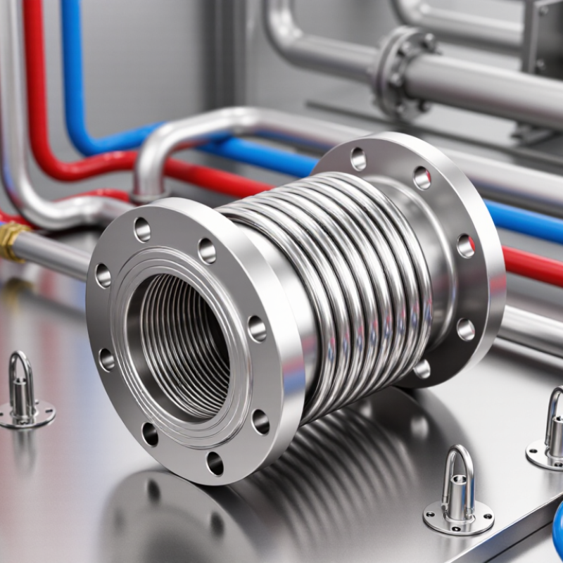
Choosing the right Bellow Compensator is a practical engineering decision, not a simple catalogue search. Pipe systems expand, contract, vibrate, and shift under pressure. A suitable compensator must absorb these movements without creating new stress points. Temperature, pressure, media, pipe size, and installation space all matter.

Begin with accurate operating data. Record the maximum temperature, working pressure, movement direction, cycle frequency, and fluid characteristics. Stainless steel bellows may suit many applications, but corrosive chemicals or abrasive particles can demand different materials. Consider axial, lateral, and angular movement separately. A model designed for axial expansion may perform poorly during repeated lateral deflection. It happens more often than expected.

Connection type also affects reliability. Flanged units simplify maintenance, while welded designs may reduce leakage risks when installed correctly. Liners can protect the bellows from high flow velocity and turbulence. Guides, anchors, and fixed points must support the system design. Even a high-quality Bellow Compensator can fail when surrounding pipework is poorly aligned.

Reliable selection combines manufacturer data, engineering calculations, and field experience. Check pressure ratings at the actual operating temperature, not only at room temperature. Review fatigue life, spring rate, weld quality, inspection records, and test certificates. Independent technical advice can help when the application involves steam, vacuum, cryogenic service, or frequent thermal cycling. No selection guide is perfect. Site conditions change, measurements can be incomplete, and assumptions require review. A careful decision leaves room for verification before purchase and inspection after installation.

How to Choose the Right Bellow Compensator?

Define the Operating Conditions for a Bellow Compensator

How to Choose the Right Bellow Compensator?

Define the Operating Conditions for a Bellow Compensator

Selecting a bellows compensator starts with real operating data, not a catalog size. Record the fluid, pressure, temperature, pipe diameter, and connection type. Note the lowest and highest temperatures, including short-term changes during startup and shutdown. Steam, hot oil, chilled water, and corrosive gases create very different design demands.

Movement must be measured in three directions. Define axial extension or compression, lateral offset, and angular deflection. Estimate the number of operating cycles over the equipment’s service life. A unit moving twice daily may need a different fatigue design than one moving every few minutes. Leave room for uncertainty. Field movement is sometimes greater than the original drawing suggests.

Check nearby anchors, guides, supports, and equipment nozzles before choosing the compensator. An anchor that is too weak can transfer excessive force into the pipe system. A guide installed too far away may allow unwanted buckling. I have seen otherwise suitable units fail because installation conditions were ignored. That mistake is avoidable, but not always obvious.

Confirm pressure ratings at the actual design temperature, not only at room temperature. Review material compatibility, allowable movement, spring rate, and fatigue calculations with a qualified engineer. Ask for inspection records, dimensional checks, and pressure-test evidence. If the operating profile is incomplete, state the assumptions clearly and revisit them before fabrication. Small omissions can become expensive repairs.

Match the Compensator Type to the Required Movement

How to Choose the Right Bellow Compensator?

Match the Compensator Type to the Required Movement

Movement determines the compensator type. Axial movement needs an axial bellows compensator. Lateral movement usually needs a universal or hinged design. Angular movement calls for a hinged compensator. A simple example is a pipe growing 25 millimeters from heat. An axial unit may handle it directly. A 15-millimeter sideways offset needs a different arrangement. The wrong choice can overload the bellows.

The EJMA Standards, 11th Edition, evaluates fatigue life through pressure, temperature, movement, and cycle requirements. It also considers spring rate and stress limits. ASME B31.3-2022 requires piping flexibility and pressure design checks. These checks should include anchors, guides, and connected equipment. Do not select from movement alone. A compensator may absorb 30 millimeters axially but fail under combined lateral and angular movement.

Field experience exposes another issue. Engineers sometimes trust a neat calculation too quickly. Installation misalignment, guide friction, and thermal gradients can change actual movement.

ISO 10380:2012 also highlights testing for metallic hose performance, including pressure and flexibility. Record the expected movement, cycle count, design pressure, and temperature before sizing. Short pipe runs often hide the problem. A careful site measurement may prevent an expensive redesign.

Select Materials for Temperature, Pressure, and Media Compatibility

How to Choose the Right Bellow Compensator?

Material selection starts with the real operating temperature, not the catalog maximum. The U.S. Department of Energy reports that process heating uses about 51% of industrial energy. This makes thermal cycling a serious design factor. Stainless steel suits many clean, moderate-temperature services. Nickel-based alloys may perform better in hotter or chemically aggressive systems. A simple temperature rating can mislead.

Pressure changes the choice as well. Bellows must resist pressure without losing flexibility or fatigue life. Check design pressure, vacuum conditions, cycle frequency, and axial movement together. EJMA design guidance treats fatigue life as a calculated requirement, not an assumption. In practice, a thicker wall may improve pressure resistance but reduce movement capacity. That trade-off deserves review.

The process medium can quietly cause failure. Chlorides may trigger pitting in stainless steel. Acids, caustics, and wet gases require separate compatibility checks. The NACE IMPACT study estimated global corrosion costs at 2.5 trillion dollars annually, equal to about 3.4% of global GDP. Material compatibility is not a minor detail. Specify concentration, moisture, contaminants, and cleaning chemicals. Also question the data. Laboratory compatibility does not always match a vibrating, cycling pipeline. Insulation, weld quality, and temperature gradients can change the result. A defensible selection records every assumption.

How to Choose the Right Bellow Compensator? - Select Materials for Temperature, Pressure, and Media Compatibility

Material / Bellows Type Typical Continuous Temperature Range* Pressure Suitability** Generally Compatible Media Main Limitations Typical Applications
304 Stainless Steel Approximately −196 to 550°C Suitable for low-to-moderate pressure when properly formed and rated; external pressure or vacuum requires design verification. Air, water, steam, many dry gases, and general industrial fluids. Less resistant than 316L to chlorides, seawater, and some chemical environments; susceptible to chloride stress-corrosion cracking at elevated temperature. General piping expansion, exhaust systems, thermal movement, and clean industrial services.
316L Stainless Steel Approximately −196 to 550°C Suitable for low-to-moderate pressure and cyclic movement; pressure rating depends on ply count, diameter, convolution geometry, and fatigue life. Water, steam, many process chemicals, food-processing fluids, and mildly corrosive media. Not universally resistant to concentrated chlorides, strong reducing acids, or highly corrosive chemicals. Chemical processing, hygienic systems, marine-adjacent equipment, and cryogenic piping.
Nickel Alloy Bellows Commonly approximately −196 to 700°C, depending on alloy and design Can be selected for higher temperature, pressure, and corrosion duty than standard stainless steel; engineering qualification is essential. High-temperature gases, corrosive process fluids, reducing or oxidizing environments, and selected acids or alkalis. Higher cost; exact compatibility varies significantly by alloy and concentration. Refineries, chemical plants, high-temperature equipment, and severe-service piping.
PTFE-Lined or PTFE Bellows Approximately −60 to 200°C, grade and pressure dependent Generally used for low-to-moderate pressure; creep, wall thickness, and vacuum stability must be checked. Most acids, many alkalis, solvents, aggressive chemicals, and high-purity fluids. Limited resistance to molten alkali metals, elemental fluorine, some high-temperature fluorinating agents, and mechanical creep under sustained load. Corrosive chemical transfer, laboratory systems, semiconductor processes, and sanitary applications.
EPDM Rubber Approximately −45 to 150°C Suitable for low pressure and flexible movement; pressure capability decreases with temperature and larger diameters. Hot water, steam, dilute acids, dilute alkalis, ozone, and weathering environments. Poor compatibility with petroleum oils, mineral oils, fuels, and many hydrocarbon-based fluids. Water systems, heating equipment, HVAC, outdoor installations, and steam service.
NBR Rubber Approximately −30 to 100°C Suitable for low-to-moderate pressure in oil and fuel service; verify compression, temperature, and cycle requirements. Mineral oils, hydraulic oils, fuels, greases, and many aliphatic hydrocarbons. Limited resistance to ozone, sunlight, weathering, strong acids, and high-temperature applications. Hydraulic systems, fuel lines, oil transfer, and general industrial machinery.
FKM Rubber Approximately −20 to 200°C Suitable for low-to-moderate pressure, especially where high-temperature sealing and fluid resistance are required. Fuels, mineral oils, lubricants, many hydrocarbons, and elevated-temperature fluids. Poor resistance to hot water and steam, some amines, strong alkalis, and certain low-molecular-weight organic acids. Automotive systems, fuel handling, oil and gas equipment, and high-temperature seals.
Graphite / Flexible Graphite Approximately −200 to 450°C in oxidizing service; higher temperatures may be possible in inert atmospheres Used mainly in high-temperature sealing systems; pressure capability depends on reinforcement, packing structure, and containment design. Steam, hydrocarbons, many chemicals, and high-temperature gases. Oxidizes at elevated temperature in air; not suitable for every strongly oxidizing medium and may require protective construction. High-temperature valves, thermal equipment, exhaust systems, and severe-service sealing.
Selection notes: *Temperature ranges are typical guidance values, not guaranteed operating limits. **A bellows compensator’s allowable pressure is determined by its complete design, including diameter, wall thickness, number of plies, convolution geometry, end connections, movement, cycle life, and safety factor. Always confirm the final rating against the actual temperature, pressure, vacuum, movement, corrosion, and fatigue requirements.

Check Connection Design, Space Limits, and Installation Requirements

How to Choose the Right Bellows Compensator?

Connection design should match the pipe system, movement pattern, and operating conditions. Check whether the joint requires flanged, welded, or another approved connection. Confirm pressure rating, temperature range, material compatibility, and expected axial or lateral movement. A small mismatch can create serious stress at the connection. Ask a qualified engineer to verify the design against applicable piping codes.

Space limits often affect the selection more than expected. Measure the face-to-face length, nearby valves, insulation thickness, and access for inspection. Allow room for the compensator to move without touching guides, supports, or structural steel. A compact unit may fit the drawing but fail in the field. I have seen installation plans miss maintenance clearance. That mistake is easy to make.

Tips: Keep the bellows aligned with the pipe centerline. Use anchors and guides as designed. Remove shipping restraints only after final positioning. Never force the compensator to correct poor pipe alignment. Check welds for slag, spatter, and distortion. Record cold settings before operation. Recheck bolts after initial thermal cycling. One detail matters. Review the installation sequence with the site team, because a technically correct design can still be installed incorrectly.

Verify Performance, Maintenance Needs, and Service Life

How to Choose the Right Bellow Compensator?

Selecting the right bellow compensator begins with operating facts, not catalog appearance. Record temperature, pressure, movement, medium, and cycle frequency. A unit that fits one dimension may fail under repeated thermal expansion. Ask for verified test data. Check pressure ratings at actual temperature, not room conditions. Confirm axial, lateral, and angular movement separately. They are not interchangeable. Numbers matter.

Maintenance planning should be practical. Inspect bellows for dents, corrosion, uneven folds, and nearby weld damage. Look for unexpected movement after startup. That small change may indicate poor guiding or excessive vibration. Check anchors, guides, liners, and hardware during scheduled shutdowns. Keep records with dates, temperatures, and observed movement. This supports better decisions. Do not assume a clean exterior means healthy metal. Internal erosion can remain invisible, especially with abrasive or chemically active media.

Service life depends on cycles, stroke, installation alignment, and environment. Request a fatigue-life calculation based on expected cycles, not a generic figure. Add a sensible safety margin. Real systems rarely behave perfectly. In field inspections, rushed installation often shortens service life faster than modest design errors. Still, that observation needs site evidence. Review operating logs and compare predicted cycles with actual demand. If conditions change, recalculate. A compensator selected this way supports safer maintenance intervals and more predictable replacement planning.